RoofViews

Building Science

Is your Cold Storage energy use through the roof?

By Kristin Westover

April 21, 2021

Cold storage facility for fresh produce

This piece is co-written by Jennifer Keegan, AAIA.


The headaches of Cold Storage facility operations extend beyond making sure the ice cream doesn't melt. Owners and Operators are regularly challenged with:

  • Selecting a cost-effective roof system that is going to be long-lasting
  • Working around unsafe areas in the interior due to ice accumulation
  • Struggling to reduce monthly energy bills

For Owners who are looking to increase energy savings and safety records, your roof not only keeps the weather out, but can help resolve these operational issues.

_____________

Cold Storage buildings are designed to maintain cold temperatures, much colder temperatures than a typical building. Cold storage facilities, such as blast freezers, may be required to maintain an interior temperature of minus 50 degrees Fahrenheit. Having a structure that is properly insulated and sealed to maintain the required temperature and minimize ice build-up is important not only for the products being stored inside, but also for potential energy savings over the life of the facility.

How can roofing materials impact energy savings?

Think of the walls of the Cold Storage facility as a jacket, and the roof as a hat. When it is cold outside, you want to make sure that you have a jacket and a hat to insulate and keep you warm. The same idea applies to a Cold Storage facility — the roof and walls of the structure insulate the products inside. But in this case, when it's warm outside, they keep the products inside cold. Not having enough insulation, on either the walls or the roof, will make your mechanical systems work harder to maintain the interior temperatures, which increases energy use, and can result in higher energy bills.

The effectiveness of roof insulation is determined by its R-value. According to Energy Star, R-value is a measure of an insulation's ability to resist heat traveling through it. The higher the R-value, the better the thermal performance of the insulation and its effectiveness at maintaining interior temperatures. R-value is typically expressed as a value per inch of insulation, and the recommended R-value of Cold Storage spaces will vary based on the interior temperature, although they are much higher than typically recommended for a traditional building. For comparison, a traditional office building may require an R-value of 30. In the 2018 edition of the American Society of Heating, Refrigeration and Air Conditioning Engineers' ASHRAE Handbook – Refrigeration, there are suggested minimum R-values for Roof Insulation between 30 and 60, depending on the cold storage type.

R-values will vary by product, including factors such as thickness and density. When calculating the total R-value of a multilayered installation, adding the R-values of the individual layers will provide the total R-value in the system. Particularly in Cold Storage, it makes sense to select an insulation that provides a higher R-value per inch, such as Polyisocyanurate (Polyiso, R-5.6 per inch), Extruded Polystyrene (XPS R-5.0 per inch), or Expanded Polystyrene (EPS R-3.8 per inch).

While insulations come in many thicknesses, it is a best practice to install several layers of thinner insulation rather than one or two layers of thicker insulation in order to reduce thermal bridging. Thermal bridging occurs when insulation is discontinuous between joints, allowing for air and thermal movement between the joints or gaps between boards. During installation, the use of several layers of insulation allows for staggering and offsetting the insulation joints, and blocks the passages that allow for air to bypass the insulation. Limiting thermal bridging can increase energy efficiency as it limits air movement between insulation boards.

Figure 1: Lower energy efficiency resulting from air movement between boards and fasteners acting as a thermal bridge.

Adding the adequate amount of insulation will prevent uncontrolled loss of the interior conditioned air, as well as assist in maintaining the required interior temperatures. Better maintaining the interior conditioned temperatures means that the cooling systems are required to run less often, which can equate to energy savings. While there may be an additional upfront cost to install an additional layer of insulation to increase the overall R-value of the roof, the cost should be minimal compared to the long-term savings of the added insulation. Of course, energy cost savings are not guaranteed and the amount of savings may vary based on climate zone, utility rates, radiative properties of roofing products, insulation levels, HVAC equipment efficiency and other factors.

What about the roof membrane? While there are many choices when it comes to the type of membrane, the most common discussion revolves around the color of the membrane. For a typical building, maintaining a comfortable space involves both heating and cooling, depending on the season. For the typical building, the color selection of the membrane has a greater effect when the interior of the building is being cooled. A highly reflective (light colored) roof membrane offers extra benefits when the interior is being cooled, because it will reflect heat from the sun. Similarly, for a Cold Storage building, it is beneficial to select a lighter-colored roof in order to reflect the heat from the sun to assist in reducing the already high costs related to cooling the building. Reflecting heat from the sun will decrease the heat radiating into the interior, which means the cooling equipment will not have to work as hard to maintain interior temperatures, and will ultimately work more efficiently.

What about roof attachment? We discussed the concept of thermal bridging and how energy loss occurs at discontinuities between the joints of the insulation, but thermal bridging can also occur where there are fastener penetrations through the roof system, as seen in Figure 1. Fasteners are used to attach the insulation and the membrane to the roof deck, which is referred to as a mechanically attached system. A way to reduce the thermal bridging that occurs at fastener penetrations is to bury them in the system or eliminate them altogether and install an adhered roof system. An adhered roof system typically fastens the bottom layer of insulation to the deck level and then subsequent layers of insulation, membrane and coverboard, are adhered. By eliminating the fasteners, the path for air to travel into the roof system is also reduced.

Figures 2 and 3 illustrate good and better scenarios, in terms of limiting thermal bridging and reducing air flow into the roof assembly. In Figure 2, labeled as the 'good' scenario, there are multiple layers of insulation, staggered and offset, but they are mechanically attached to the deck. While the staggered insulation layers limit some of the air flow into the roof assembly, air is still able to travel throughout the roof. In Figure 3, labeled as the 'better' scenario, only the first layer of insulation is mechanically attached and subsequent layers are adhered. By adhering the subsequent layers, air flow into the roof assembly is greatly reduced. Reducing air flow assists in maintaining interior temperatures, which can result in energy savings for the facility.

Figure 2: "Good Scenario" with staggered and offset insulation and a mechanically attached roof membrane.

Figure 3: "Better Scenario" with the first layer of insulation mechanically attached and subsequent layers of the roof system adhered, greatly reducing the air flow into the roof assembly.

The Devil is in the Details

The result of limiting air flow through the roof assembly of a Cold Storage facility is not a matter of occupant comfort, but a matter of occupant safety. In a traditional building, such as an office building, a poorly detailed roof termination could result in drafty offices or temperature complaints. In a Cold Storage facility, those same drafts condense due to the large temperature differential between the interior and exterior and the condensation can turn into ice. The ice can form on various surfaces including locations where air leakage is occurring, such as at roof-to-wall interfaces, but also on the Cold Storage floors where the surface of the floor is cooler than the air above it. When ice forms on the floors, it can cause slips, trips, or falls, and can also impact operations if a particular area of the facility has to be avoided.

Ice formation inside a Cold Storage facility is the result of improperly designed or executed details. Details, such as those at the wall-to-roof interface, or sealing around penetrations, are crucial to not only keep out rain, but to conserve energy within the facility. Similar to the loss of energy created by thermal bridging, air flow through the roof created by poor detailing results in considerable loss of the cooled temperatures required in the space below. Additionally, air flow that condenses can collect within the roof assembly, including within the insulation, and freeze. Frozen insulation is a common side effect of a Cold Storage roof that is not functioning properly. Frozen insulation is exactly what it sounds like — insulation that has had moisture accumulate within it and then freezes. Frozen insulation has properties similar to wet insulation and is ineffective, since it provides virtually no insulating properties. A frozen roof is almost like having no insulation at all, and the energy used to maintain the interior temperatures goes through the roof!

Proper detailing of a Cold Storage facility begins during the planning stage. Determining the type of interior spaces, the sizes, and the overall usage of the facility should be taken into consideration. Once the overall layout of the Cold Storage facility is decided, the construction materials, including the roof assembly, will need to be determined. Once the roof assembly is selected, design of the roof details is crucial. Typical details, including roof-to-wall interface and penetrations, must be meticulously thought out and designed.

Roof-to-wall interfaces and penetrations must be sealed to prevent air from entering into the roof assembly. Even the smallest gap that allows air flow can have detrimental effects on the roof assembly. The most common method of ensuring sealed terminations and penetrations is the use of a closed-cell spray foam. Closed-cell spray foam is typically installed at the intersection of the exterior walls and the roof insulation at a width of one inch and extends from the deck level to the top of the insulation. At wall-to-steel deck intersections, it is also best practice to install spray foam in the deck flutes a minimum of 12 inches from the wall. The closed cell spray foam helps to seal the interface so air cannot enter into the roof assembly.

Figure 4: GAF Detail 201C Coated Metal Roof Edge at Insulated Wall Panel

Proper execution of the roof installation is critical and requires a contractor with Cold Storage construction experience. Having the right partner who understands the importance of their role in the project and collaborates with the team can make or break the project. A future article will dive into these details. In the meantime, for information on GAF-certified contractors, talk to GAF first.

The benefits outweigh the risks. Seemingly insignificant decisions made during the design and construction of the roof of a Cold Storage facility can impact the functionality and energy usage of the building for the lifetime of the roof system, which is typically 25-35 years. Once air leakage occurs into a roof assembly, the damage that occurs is often irreversible. Ice accumulation on the floor can be a serious hazard for occupants and workers. The challenge of identifying where the breaches in the roof assembly occur, let alone remediation, can be difficult and costly. Remediation of the identified problems generally includes removal of frozen insulation as well as addressing the identified problem areas which are often attributed to detailing and air leakage. The associated consequence of a poorly designed and installed roof is the cost of the energy loss. Mechanical equipment having to work harder to maintain temperatures will result in higher costs due to an increase in energy use, and the effect of the equipment working harder often leads to premature mechanical failures. The benefits associated with designing and installing a proper Cold Storage roof far outweigh the risks. A properly designed and constructed roof will save energy, prolong the life of mechanical equipment, and protect both the building's occupants and the goods being stored inside the facility.

Need to talk to an expert regarding Cold Storage roof design? Talk to GAF first. Email us at coldstorage.assistance@gaf.com for design questions, detailing assistance, and expert advice.

About the Author

Kristin Westover, P.E., LEED AP O+M, is a Technical Manager of Specialty Installations for low-slope commercial roofing systems at GAF. She specializes in cold storage roofing assemblies where she provides insight, education, and best practices as it relates to cold storage roofing. Kristin is part of the Building and Roofing Science Team where she works with designers on all types of low-slope roofing projects to review project design considerations so designers can make informed roof assembly decisions.

Related Articles

Flat roof with hot air welded pvc membrane waterproofing for ballasted system
Building Science

Thermal Bridging Through Roof Fasteners: Why the Industry Should Take Note

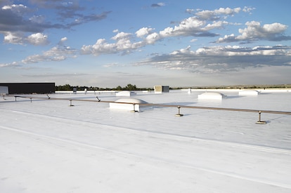
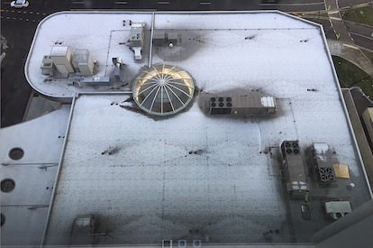
What is going on here?No, this roof does not have measles, it has a problem with thermal bridging through the roof fasteners holding its components in place, and this problem is not one to be ignored.As building construction evolves, you'd think these tiny breaches through the insulating layers of the assembly, known as point thermal bridges, would matter less and less. But, as it happens, the reverse is true! The tighter and better-insulated a building, the bigger the difference all of the weak points, in its thermal enclosure, make. A range of codes and standards are beginning to address this problem, though it's important to note that there is often a time lag between development of codes and their widespread adoption.What Is the Industry Doing About It?Long in the business of supporting high-performance building enclosures, Phius (Passive House Institute US) provides a Fastener Correction Calculator along with a way to calculate the effect of linear thermal bridges (think shelf angles, lintels, and so on). By contrast, the 2021 International Energy Conservation Code also addresses thermal bridging, but only considers framing materials to be thermal bridges, and actually pointedly ignores the effects of point loads like fasteners in its definition of continuous insulation: "insulation material that is continuous across all structural members without thermal bridges other than fasteners and service openings" (Section C202). Likewise, The National Energy Code of Canada for Buildings: 2020 addresses thermal bridging of a number of building components, but also explicitly excludes fasteners: "in calculating the overall thermal transmittance of assemblies…fasteners need not be taken into account" (Section 3.1.1.7.3). Admittedly, point thermal bridges are often excluded because it is challenging to assess them with simple simulation tools.Despite this, researchers have had a hunch for decades that thermal bridging through the multitude of fasteners often used in roofs is in fact significant enough to warrant study. Investigators at the National Bureau of Standards, Oak Ridge National Laboratory, the National Research Council Canada, and consulting firms Morrison Hershfield and Simpson Gumpertz & Heger (SGH), have conducted laboratory and computer simulation studies to analyze the effects of point thermal bridges.Why Pay Attention Now?The problem has been made worse in recent years because changes in wind speeds, design wind pressures, and roof zones as dictated by ASCE 7-16 and 7-22 (see blogs by Jim Kirby and Kristin Westover for more insight), mean that fastener patterns are becoming denser in many cases. This means that there is more metal on average, per square foot of roof, than ever before. More metal means that more heat escapes the building in winter and enters the building in summer. By making our buildings more robust against wind uplift to meet updated standards, we are in effect making them less robust against the negative effects of hot and cold weather conditions.So, how bad is this problem, and what's a roof designer to do about it? A team of researchers at SGH, Virginia Tech, and GAF set out to determine the answer, first by simplifying the problem. Our plan was to develop computer simulations to accurately anticipate the thermal bridging effects of fasteners based on their characteristics and the characteristics of the roof assemblies in which they are used. In other words, we broke the problem down into parts, so we could know how each part affects the problem as a whole. We also wanted to carefully check the assumptions underlying our computer simulation and ensure that our results matched up with what we were finding in the lab. The full paper describing our work was delivered at the 2023 IIBEC Convention and Trade Show, but here are the high points, starting with how we set up the study.First, we began with a simple 4" polyisocyanurate board (ISO), and called it Case A-I.Next, we added a high-density polyisocyanurate cover board (HD ISO), and called that Case A-II.Third, we added galvanized steel deck to the 4" polyiso, and called that Case A-III.Finally, we created the whole sandwich: HD ISO and ISO over steel deck, which was Case A-IV.Note that we did not include a roof membrane, substrate board, air barrier, or vapor retarder in these assemblies, partly to keep it simple, and partly because these components don't typically add much insulation value to a roof assembly.The cases can be considered base cases, as they do not yet contain a fastener. We needed to simulate and physically test these, so we could understand the effect that fasteners have when added to them.We also ran a set of samples, B-I through B-IV, that corresponded with cases A-I through A-IV above, but had one #12 fastener, 6" long, in the center of the 2' x 2' assembly, with a 3" diameter insulation plate. These are depicted below. The fastener penetrated the ISO and steel deck, but not the HD ISO.One visualization of the computer simulation is shown here, for Case B-IV. The stripes of color, or isotherms, show the vulnerability of the assembly at the location of the fastener.What did we find? The results might surprise you.First, it's no surprise that the fastener reduced the R-value of the 2' x 2' sample of ISO alone by 4.2% in the physical sample, and 3.4% in the computer simulation (Case B-I compared to Case A-I).When the HD ISO was added (Cases II), R-value fell by 2.2% and 2.7% for the physical experiment and computer simulation, respectively, when the fastener was added. In other words, adding the fastener still caused a drop in R-value, but that drop was considerably less than when no cover board was used. This proved what we suspected, that the HD ISO had an important protective effect against the thermal bridging caused by the fastener.Next, we found that the steel deck made a big difference as well. In the physical experiment, the air contained in the flutes of the steel deck added to the R-value of the assembly, while the computer simulation did not account for this effect. That's an item that needs to be addressed in the next phase of research. Despite this anomaly, both approaches showed the same thing: steel deck acts like a radiator, exacerbating the effect of the fastener. In the assemblies with just ISO and steel deck (Cases III), adding a fastener resulted in an R-value drop of 11.0% for the physical experiment and 4.6% for the computer simulation compared to the assembly with no fastener.Finally, the assemblies with all the components (HD ISO, ISO and steel deck, a.k.a. Cases IV) showed again that the HD ISO insulated the fastener and reduced its negative impact on the R-value of the overall assembly. The physical experiment had a 6.1% drop (down from 11% with no cover board!) and the computer simulation a 4.2% drop (down from 4.6% with no cover board) in R-value when the fastener was added.What Does This Study Tell Us?The morals of the study just described are these:Roof fasteners have a measurable impact on the R-value of roof insulation.High-density polyisocyanurate cover boards go a long way toward minimizing the thermal impacts of roof fasteners.Steel deck, due to its high conductivity, acts as a radiator, amplifying the thermal bridging effect of fasteners.What Should We Do About It?As for figuring out what to do about it, this study and others first need to be extended to the real world, and that means making assumptions about parameters like the siting of the building, the roof fastener densities required, and the roof assembly type.Several groups have made this leap from looking at point thermal bridges to what they mean for a roof's overall performance. The following example was explored in a paper by Taylor, Willits, Hartwig and Kirby, presented at the RCI, Inc. Building Envelope Technology Symposium in 2018. In that paper, the authors extended computer simulation results from a 2015 paper by Olson, Saldanha, and Hsu to a set of actual roofing scenarios. They found that the installation method has a big impact on the in-service R-value of the roof.They assumed a 15,000-square-foot roof, fastener patterns and densities based on a wind uplift requirement of 120 pounds per square foot, and a design R-value of R-30. In this example, a traditional mechanically attached roof had an in-service R-value of only R-25, which is a 17% loss compared to the design R-value.An induction-welded roof was a slight improvement over the mechanically attached assembly, with an in-service value of only R-26.5 (a 12% loss compared to the design R-value).Adhering instead of fastening the top layer of polyiso resulted in an in-service R-value of R-28.7 (a 4% loss compared to the design R-value).Finally, in their study, an HD polyiso board was used as a mechanically fastened substrate board on top of the steel deck, allowing both layers of continuous polyiso insulation and the roof membrane to be adhered. Doing so resulted in an in-service R-value of R-29.5, representing only a 1.5% loss compared to the design R-value.To operationalize these findings in your own roofing design projects, consider the following approaches:Consider eliminating roof fasteners altogether, or burying them beneath one or more layers of insulation. Multiple studies have shown that placing fastener heads and plates beneath a cover board, or, better yet, beneath one or two layers of staggered insulation, such as GAF's EnergyGuard™ Polyiso Insulation, can dampen the thermal bridging effects of fasteners. Adhering all or some of the layers of a roof assembly minimizes unwanted thermal outcomes.Consider using an insulating cover board, such as GAF's EnergyGuard™ HD or EnergyGuard™ HD Plus Polyiso cover board. Installing an adhered cover board in general is good roofing practice for a host of reasons: they provide enhanced longevity and system performance by protecting roof membranes and insulation from hail damage; they allow for enhanced wind uplift and improved aesthetics; and they offer additional R-value and mitigate thermal bridging as shown in our recent study.Consider using an induction-welded system that minimizes the number of total roof fasteners by dictating an even spacing of insulation fasteners. The special plates of these fasteners are then welded to the underside of the roof membrane using an induction heat tool. This process eliminates the need for additional membrane fasteners.Consider beefing up the R-value of the roof insulation. If fasteners diminish the actual thermal performance of roof insulation, building owners are not getting the benefit of the design R-value. Extra insulation beyond the code minimum can be specified to make up the difference.Where Do We Go From Here?Some work remains to be done before we have a computer simulation that more closely aligns with physical experiments on identical assemblies. But, the two methods in our recent study aligned within a range of 0.8 to 6.7%, which indicates that we are making progress. With ever-better modeling methods, designers should soon be able to predict the impact of fasteners rather than ignoring it and hoping for the best.Once we, as a roofing industry, have these detailed computer simulation tools in place, we can include the findings from these tools in codes and standards. These can be used by those who don't have the time or resources to model roof assemblies using a lab or sophisticated modeling software. With easy-to-use resources quantifying thermal bridging through roof fasteners, roof designers will no longer be putting building owners at risk of wasting energy, or, even worse, of experiencing condensation problems due to under-insulated roof assemblies. Designers will have a much better picture of exactly what the building owner is getting when they specify a roof that includes fasteners, and which of the measures detailed above they might take into consideration to avoid any negative consequences.This research discussed in this blog was conducted with a grant from the RCI-IIBEC Foundation and was presented at IIBEC's 2023 Annual Trade Show and Convention in Houston on March 6. Contact IIBEC at https://iibec.org/ or GAF at BuildingScience@GAF.com for more information.

By Authors Elizabeth Grant

November 17, 2023

Commercial Roof
Building Science

IBC and FM—What's the Difference When it Comes to Wind Design?

IntroductionWind design of roof systems can be confusing from an engineering perspective. Wind design can also be confusing because the International Building Code (IBC) provides specific requirements, but so does Factory Mutual (FM). If FM is specified, do the IBC requirements need to be followed? What is the wind-design strategy for FM-insured and non-FM-insured buildings? This blog will discuss the following:IBC is a model code; FM is an insurance companyCompliance with the local building code is a legal requirement; FM is elective (a building owner has the ability to select their insurance carrier)IBC references the ASCE 7 standard; FM provides wind-design methodology via the Ratings Calculator and Assembly Search functions within RoofNavFM-insured buildings must comply with both the IBC and FM requirementsSpecifying "FM" could trigger the "FM process" unknowingly for non-FM insured buildingsWhat is the issue?In roofing specifications, architects have been referencing Factory Mutual (FM) for many decades, especially when it comes to wind design of commercial roofing systems. "Meet FM requirements," "Provide a 1-90 roof system," or just simply "Meet FM" are phrases inserted into specifications. Do these phrases supplant the need to follow the wind-design requirement of the International Building Code (IBC)? (Spoiler alert: The answer is a resounding "NO".)The BasicsThe IBC is a model code, developed by the International Code Council. A model code, such as the IBC, is intended to be adopted by municipalities (e.g., state, city) as the locally enforced building code. The model code can be adopted as-is, or with language removed, with language added, or both. The local building code is enforced through local building code officials. And, very importantly, meeting the local building code is a legal requirement and there can be ramifications when the local building code is not met.Commercial buildings are required to meet the IBC as adopted and amended by the local jurisdiction. For wind design, the IBC requires a roof system be designed based on ASCE 7, Minimum Design Loads for Buildings and Other Structures. (More on the specifics later.)FM Global is an insurance company and a purveyor of design and installation documents for roof systems (e.g., Loss Prevention Data Sheets 1-28, Wind Design). FM Approvals is a testing facility, a third-party certification body, and a developer of Approval Standards (e.g., FM 4470, Single-Ply, Polymer-Modified Bitumen Sheet, Built-Up Roof (BUR) and Liquid Applied Roof Assemblies for use in Class 1 and Noncombustible Roof Deck Construction). FM Approvals also maintains RoofNav (www.RoofNav.com), which provides access to FM Approved roofing systems and related installation recommendations from FM Global. RoofNav is likely the FM tool that is frequently used by architects and roof system designers who are searching for and selecting approved roof systems. This is why many architects and specifiers include some reference to FM in roof system specifications.IBC Wind Design MethodModel building codes, such as the 2018 IBC, when adopted by a local jurisdiction, become the legal requirements for construction. The IBC specifically states, "The I-Codes, including this International Building Code, are used in a variety of ways in both the public and private sectors. Most industry professionals are familiar with the I-Codes as the basis of laws and regulations in communities across the U.S. and in other countries." A more succinct way of stating this is—the local building code is the law.Within the IBC, the building code requirements for roofing and rooftop construction are found in Chapter 15, Roof Assemblies and Rooftop Structures. Section 1501.1, Scope, states "The provisions of this chapter shall govern the design, materials, construction and quality of roof assemblies, and rooftop structures." Wind resistance of roof systems is included in Section 1504, Performance Requirements, and Section 1504.1, Wind resistance of roofs, requires roofs be designed for wind loads according to Chapter 16, Structural Design.Section 1609, Wind Loads, incorporates by reference the standards set forth in ASCE 7; this section includes the following language."1609.1.1 Determination of wind loads. Wind loads on every building or structure shall be determined in accordance with Chapters 26 to 30 of ASCE 7."It's worth noting that the version (i.e., year of publication) of ASCE 7 is not specified in the body of the code; versions of referenced standards are found in Chapter 35.The key point is that the IBC directs users to ASCE 7 to determine design wind pressures (DWP) for roof systems.To continue a bit deeper into the 2018 IBC, Section 1504.3 is the directive to designers to design roofs to resist design wind pressures."1504.3 Wind resistance of non ballasted roofs. Roof coverings installed on roofs in accordance with Section 1507 that are mechanically attached or adhered to the roof deck shall be designed to resist the design wind load pressures for components and cladding in accordance with section 1609.5.2."It's important to recognize that Section 1504.3 specifically ties the wind design of nonballasted roofs to ASCE 7 by referencing a subsection of Section 1609.Additionally, Section 1504.3.1 is the directive to manufacturers to test roof systems to determine wind uplift capacity."1504.3.1 Other roof systems. Built-up, modified bitumen, fully adhered or mechanically attached single-ply roof systems, metal panel roof systems applied to a solid or closely fitted deck and other types of membrane roof coverings shall be tested in accordance with FM 4474, UL 580 or UL 1897."This section provides 3 code-approved test methods to choose from to perform wind-uplift-capacity testing.FM 4474, American National Standard for Evaluation of Simulated Wind Uplift Resistance of Roof Assemblies Using Static Positive and/or Negative Differential PressuresUL 580, Standard for Tests for Uplift Resistance of Roof AssembliesUL 1897, Standard for Uplift Tests for Roof Covering SystemsThese tested systems are found in Approval Listings from organizations like FM, UL, and SPRI. These two videos provide more information about FM Approval's RoofNav and SPRI's Directory of Roofing Assemblies.What's NOT Stated in the IBCNothing in the model code sections referenced here or any other related model code sections within IBC contains a provision that allows a wind-design method other than ASCE 7 to be used. In other words, using FM's RoofNav for wind design of roof systems is not a replacement for following building code requirements that mandate the use of ASCE 7. Of course, designers should always check with the specific requirements of the local building code to determine if the use of FM's RoofNav is allowed for code compliance.FMWe've established that FM Global is an insurance company that provides installation recommendations and FM Approvals provides design information, as well as FM-approved listings. In order to receive an FM Approval Listing, a roof system must be tested in accordance with FM 4470, Single-Ply, Polymer-Modified Bitumen Sheet, Built-Up Roof (BUR) and Liquid Applied Roof Assemblies for use in Class 1 and Noncombustible Roof Deck Construction.FM 4470 includes a battery of tests intended to help determine the long-term performance of a roof system (clearly an important issue for an insurance carrier!).FM 4470 includes the following mandatory tests to be performed:Combustibility (from above and below the roof deck)Wind uplift (FM 4474 is the test method used to determine wind uplift capacity)Hail resistanceWater leakageFoot trafficCorrosionSusceptibility to heat damageFM 4470 also includes requirements for a manufacturer's in-house quality control program that includes an audit program, field inspections during installation, and additional manufacturer responsibilities if products' construction or components are revised.The use of FM 4470 results in a roof system with a "1-60" or "1-75" listing, for example. The "1" represents the roof system is Class 1 for fire resistance (combustibility) from below the deck. The second (e.g., 60, 75) represents the wind-uplift capacity (in pounds per square foot) of the roof system.It is important to recognize that FM 4470 is not listed as one of the test methods for wind-uplift capacity in the 2018 IBC, which means the IBC does not require a roof system to be FM-approved!FM 4474, American National Standard for Evaluation of Simulated Wind Uplift Resistance of Roof Assemblies Using Static Positive and/or Negative Differential Pressures, is a test method to determine wind uplift capacity of roof systems. As noted previously, FM 4474 is the wind-uplift test method that is required to be used within FM 4470 for an FM Approval Listing.FM-insured buildingsBuildings that are FM insured are commonly required by FM to use a roof system that has an FM Approval Listing. More specifically, roof systems intended to be used on FM-insured buildings should use RoofNav to determine wind loads (via the RoofNav Ratings Calculator) and find Approved roof systems (via the RoofNav Assembly Search).Non FM-insured BuildingsTo broadly say "Meet FM" or "Meet FM requirements" in a spec could be interpreted to mean—for non-FM insured buildings—that the wind-design process, deck securement, and roof system installation should follow ALL of the specific FM processes and recommendations that are used for FM-insured buildings.As the architect or specifier working on a building that is not insured by FM, is the vague specification language truly intended to bring the entire "FM process" into the wind design and installation of a roof system? Probably not. It is more likely the vague specification language referencing FM is intended to be a way to state that the assembly must meet local building code requirements for wind design.Saying "Meet FM" or "Meet FM requirements" does not preempt or override the requirements of the IBC, as adopted by local building code, that are legally required to be performed by the Architect of Record when it comes to wind design of roof systems. (Additional information about code requirements for wind design can be found here.)ConclusionThe IBC, as adopted by local building codes, is required by law and references ASCE 7 as the standard to be used for determining design wind pressures for roof systems. The IBC does not include FM's wind-design process (e.g., RoofNav's Ratings Calculator and Assembly Search functions) for determining DWPs. Vague specification language referencing FM may unnecessarily bring the FM wind-design process into play.The IBC also provides 3 test methods for determining wind-uplift capacity of roof systems—UL 580, UL 1897, and FM 4474. It is important to recognize that FM 4474 is a test method used by manufacturers to determine wind-uplift capacity, and FM 4470 is a comprehensive standard covering many aspects of roof system performance. Specifying and only using FM's wind design process in lieu of following the wind-design requirements in IBC, as adopted by local building code, means the minimum legal requirements for wind design technically may not have been met.Understanding the roles that IBC and FM play in the roofing industry is key to understanding the role of the architect or specifier, and the manufacturer when it comes to wind design of roof systems.This blog is for informational purposes only and is not intended to be construed or used as professional design advice. Consult a design professional to ensure the suitability or code compliance of a particular roofing system for any particular structure.

By Authors James R Kirby

November 17, 2023

very severe hail
Building Science

Defending Against Very Severe Hail

Think that your roof doesn't need protection against hail? Think again.Severe hail events are increasing in geographic footprint and are no longer just in hail alley. The geographic region that experiences 1 inch or larger hailstones has expanded to be nearly two-thirds of the United States. Nearly 10 percent more U.S. properties, more than 6.8 million, were affected by hail in 2021 than in 2020. Coinciding with the increase in properties affected by a damaging hail event in 2021, there was also an increase in insurance claims, which rose to $16.5 billion from $14.2 billion in 2020.Figure 1: The estimated number of properties affected by one or more damaging hail events. Source: NOAA, graphed by VeriskAccording to data from Factory Mutual Insurance Company (FM Global), a leader in establishing best practices to protect buildings, the review of client losses between 2016-20, showed that the average wind/hail losses averaged $931,000 per event. That's a significant impact on a business, and it doesn't account for the other effects that a disruptive loss could have such as headaches from the process of repairing or replacing damaged roofs. As a result, designing the roof to withstand damage from hail events has become not only a best practice, but a necessity.Why does hail size matter?FM Approvals is a third-party testing and certification laboratory with a focus on testing products for property loss prevention using rigorous standards. FM Global, through the loss prevention data sheets, requires the use of FM Approved roof systems. FM Global estimates their clients lose about $130M each year on average from hail events in the United States. Given the increasing volume of severe hail events and the resulting property loss, damage, and financial impacts, FM Global added to the requirements in the FM Loss Prevention Data Sheet (LPDS) 1-34 Hail Damage in 2018. Loss Prevention Data Sheets provide FM's best advice for new construction and for Data Sheet 1-34, this includes new or reroofing projects on existing buildings. Data Sheet 1-34 provides guidelines to minimize the potential for hail damage to buildings and roof-mounted equipment. FM Global intends that the data sheets apply to its insured buildings; however, some designers use data sheets as design guidelines for buildings other than those insured by FM Global.FM's LPDS 1-34 identifies the hail hazard areas across the United States: Moderate Hail hazard area, Severe Hail hazard area, and Very Severe Hail (VSH) hazard area which are defined by hail size. Note that the VSH area roughly correlates to Hail Alley. Hail Alley receives more hailstorms, and more severe ones, compared to other parts of the country.Figure 2: FM's LPDS 1-34 map outlining the different hail categories: moderate, severe, and very severe. The Very Severe area is most commonly referred to as "Hail alley".The hail hazard areas are divided by hail size, with the Very Severe hail hazard area being the largest hail size of greater than 2 inches. As a result, roofing assemblies have to meet the most stringent hail testing for designation in the Very Severe hazard area.Figure 3: Description of FM Approval hail regions.Even if you are not in hail alley, or one of the states in FM's Very Severe Hail area, hail larger than 2 inches still has the potential to occur throughout the contiguous United States. The National Oceanic and Atmospheric Administration (NOAA) tracks weather events throughout the United States, including hail. NOAA's hail database includes information such as location, date, and magnitude (size) of the hail stone for each event. A sampling of typical data is provided below; note that several states that are outside of FM's VSH zone, had hail events that would qualify as VSH, where hail stones were recorded to be larger than 2-inches in size.Figure 4: Hail events in states that are outside of the VSH area, but qualify as VSH by size.How Do I Design For Very Severe Hail?In order for a roof assembly to achieve a hail rating, the assembly must pass a hail test. FM Approvals designs the hail tests including a different test for each hail hazard area. Hail testing generally includes the use of steel or ice balls that are dropped or launched at roof assemblies in a laboratory setting. Pass criteria vary by the test, but generally visual damage cannot be present to either the membrane or components below. Roof assemblies that pass each individual hail test are FM approved to be installed in each hail hazard area.There are thousands of FM rated assemblies and it can be difficult to choose just one. To start, it is important to note that selection consists of an entire assembly, however consideration of all roof components including the membrane, coverboard, and attachment method each play an important role in how the assembly defends against hail.Membrane selection is critical for Very Severe Hail prone regions. Thicker roof membranes, as well as higher performance grades that will remain pliable under heat and UV exposure over time and will outperform standard grade materials. Fleeceback membranes also provide an added cushion layer that buffers hail impact.Coverboard selection is a critical component of the roof system design. High compressive strength coverboards are an effective means to enhance the performance of the roof system when exposed to hail events. A coverboard will enhance the roof's long term performance by fortifying the membrane when hail strikes as well as providing a firm surface to help resist damage from typical foot traffic. It will also help the roof insulation below withstand damage from hail. While conventional gypsum coverboards and high-density polyiso coverboards provide excellent protection against foot traffic and smaller hail, they are not effective for VSH. Coverboards for VSH systems were originally limited to plywood or oriented strand board (OSB). The use of plywood and OSB is very labor intensive to install as compared to traditional gypsum coverboards, increasing the cost of the installation. Recently, coverboard manufacturers have developed glass mat roof boards which are a reinforced gypsum core with a heavy-duty coated glass mat facer. Not only do these boards provide protection against 2-inch hail and are an important part of VSH assemblies, they are also a FM Class 1 and UL Class A thermal barrier for fire rated assemblies. These boards are 5/8" thick and are 92-96 pounds per 4'x8' board; about 30 percent heavier compared to plywood yet easier to install as they can be scored and cut like a traditional gypsum board.Consideration of roof attachment method is critical for selection of VSH assemblies. Historically, mechanically attached systems were not able to pass the VSH tests; when an ice ball hit the head of the fastener or plate, the result was a laceration in the membrane. To avoid failures of the membrane at the fasteners and plates, the fasteners were traditionally buried in the system; the insulation was mechanically attached and the coverboard and membrane were adhered. This is still a common installation method and as a result, there are a large number of assemblies where the membrane and coverboard are adhered. Additionally, burying the fasteners allows for the installation of a smooth backed membrane. With the development of glass mat coverboards, there are VSH rated assemblies that can be simultaneously fastened (mechanically attached coverboard and insulation) that utilize an adhered fleece-back membrane.Figure 5: VSH systems. Left is simultaneously fastened 60 mil Fleeceback TPO over glass mat VSH roof board and Polyiso Insulation. Right is 60 mil Fleeceback TPO over glass mat VSH roof board adhered in low rise foam ribbons to mechanically attached Polyiso Insulation.Figure 6: A sample of available VSH assemblies.SummaryWhy Should We Design for VSH?Severe hail events are increasing in geographic footprint and storms with hailstones that meet Very Severe Hail criteria are occurring throughout the country. While designing for VSH is a requirement if a building falls within the VSH area and is ensured by FM Global, many owners and designers are opting for roof assemblies that can withstand VSH storms even if they are not insured by FM Global. Material selection, such as coverboard and membrane, are key components to managing this risk. Glass mat coverboards and thicker, higher grade single-ply membranes, such as fleece-back, increase the roof assembly's resistance to damage. Choosing the right roof assembly could be the difference between weathering the storm or significant damage from hail.What are the next steps?Learn about GAF's Hail Storm System Resources, and as always, feel free to reach out to the Building & Roofing Science team with questions.

By Authors Kristin Westover

January 30, 2023

Don't miss another GAF RoofViews post!

Subscribe now